Search
Chassis Design
Updated: Jan 28, 2022
"Adding power makes you faster on the straights, subtracting weight makes you faster everywhere."
- Anthony Colin Bruce Chapman
Basic requirements:
The body should be light.
It should have minimum number of components.
It should provide sufficient space for passengers and luggage.
It should withstand vibrations while in motion.
It should offer minimum resistance to air.
It should be cheap and easy in manufacturing.
It should have uniformly distributed load.
It should have long fatigue life.
It should provide good vision and ventilation.
Load cases:
The vehicle designer should know the load conditions in order to ensure the structure doesn’t fail due to some instantaneous load.
Some Basic Load Cases-
Bending-
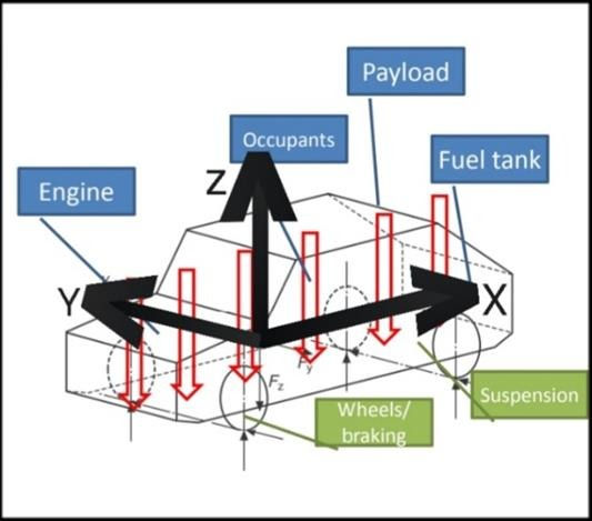
In static condition (vehicle at rest or moving with constant velocity) :
1. Loading (due to the weight of components distributed along the vehicle frame) in vertical plane (let, x-z plane) cause bending about the y-axis.
2. Unsprung mass do not impose loads in static condition.
3. Determination and Result:
Static condition vehicle structure can be treated as 2D beam because vehicle is approximate symmetry at x-y plane.
Can be solved using static equilibrium balance.
Results in set of algebraic equation.
In dynamic condition (vehicle moving at variable velocity or vehicle moving at bumpy road even at constant velocity) :
1. Inertia of the structure contributes in total loading
2. Always higher than static loading
(For road vehicles: 3 times than static loads; For off-road vehicles: 4 times than static load)
3. Determination and result:
Can be solved using dynamic equilibrium balance.
Generally results in differential equation.
Torsion-
Vehicle body is subjected to a moment applied at the axle centerlines by applying upward and downward loads at each axle. These loads result in twisting action or torsion moment about the longitudinal x-axis.
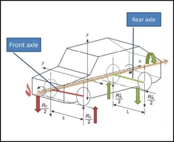
1. Cause: When vehicle traverse on an uneven road and front and rear axles experiences a moment.
2. For pure simple torsion torque is applied to one axle and reacted by the other axle.
3. Determination and Result:
Maximum torsion moment is based on the loads at the lighter loaded axle.
Load at front axle 𝑅 and at rear axle 𝑟 can be determined by;
𝒓×𝒕=𝑹×𝒇 (Where 𝑡 and 𝑓 are track width of rear and front axle)
4. Dynamic Factor:
On road: 1.3
Off road: 1.5 to 1.8
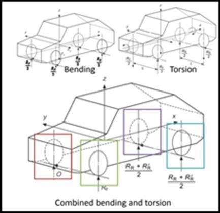
Combined bending and torsion-
1. Bending and torsional loads are super imposed. (assumed to be linear)
2. All loads of lighter axle is applied to one bending torsion wheel
3. Determination: Loads can be determined by moment balance.
Lateral Loading-
1. Generated at the tire to ground contact patch
2. Cause: Cornering
3. Result of lateral loading: When inside wheel reaction becomes zero, vehicle rollover.
4. Determination:
i) Practical:
It can either be open loop or close loop
Open loop or directional response: In this case, driver gives some input through steering and corrects it. We study both response and feedback.
Close loop: In this case, driver gives some input and we study vehicle response.
ii) Theoretical:
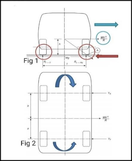
These loads are balanced by centrifugal force.
Centrifugal acceleration: 𝑉^2/𝑅=𝑔𝑡/2ℎ
Force at CG, at the moment of roll over: 𝑀𝑉2𝑅=𝑀𝑔𝑡2ℎ
Taking ΣF = 0 and ΣM = 0, it can be shown that;
Lateral force at front wheel 𝑌𝑓= (MV^2/R)* [b/(a+b)]
Lateral force at rear wheel 𝑌𝑓= (MV^2/R)* [a/(a+b)]
Width of car and reinforcement provide sufficient bending stiffness to withstand lateral force.
Longitudinal Loading-
1. Cause: When vehicles accelerate and decelerate, longitudinal loads generated
2. Determination:
During acceleration:
Weight transferred from front to back.
Taking ΣM = 0;
Reaction force on the front wheel-
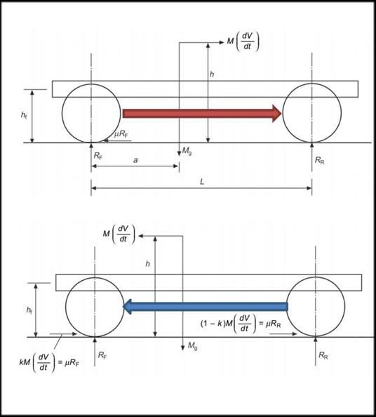
𝑅f={𝑀𝑔(𝐿−𝑎)−𝑀ℎ(𝑑𝑣/𝑑𝑡)}/𝐿
Reaction force on rear wheel-
𝑅r={𝑀𝑔(𝑎)+𝑀ℎ(𝑑𝑣/𝑑𝑡)}/𝐿
During deceleration:
Weight transferred from back to front.
Taking ΣM = 0;
Reaction force on the front wheel-
𝑅f={𝑀𝑔(𝐿−𝑎)+𝑀ℎ(𝑑𝑣/𝑑𝑡)}/𝐿
Reaction force on rear wheel-
𝑅r={𝑀𝑔(𝑎)-𝑀ℎ(𝑑𝑣/𝑑𝑡)}/𝐿
3. Tractive and braking forces add to bending through suspension.
Asymmetric Loading-
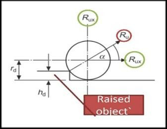
1. Cause: When one wheel strikes a raised object or drops into a pit.
2. Resolve as vertical or horizontal force.
i) Magnitude of force depends upon-
Speed of vehicle
Suspension stiffness
Wheel mass
Body mass
ii) Applied load is a shock wave-
Acts in a very less time duration
There is no change in speed
Acts through the center of the wheel
iii) Resolved vertical force causes-
Additional axle load
Vertical inertial load through CG
Torsion Moment
iv) Resolved horizontal force causes-
Bending in x-z plane
Horizontal inertial load through CG
Moment about z-axis
Some important terms to consider during chassis design:
Allowable Stress-
Vehicle structure is not fully rigid
Internal resistance or stress is induced to balance external forces
Stress should be kept to acceptable limits
Stress due to static load × dynamic factor ≤ yield stress
Fatigue analysis is needed at places of stress concentration like suspension and seat mounting points.
Bending Stiffness-
Important in structural stiffness
Determined by acceptable limits of deflection of the side frame.
The bending moment per unit width of a rectangular test piece, divided by the curvature according to the expression:
Bending stiffness 𝑆𝑏=𝑀𝑐 Bending moment/{(radius of curvature)*(width of test price)}
Panels separated by honey comb structure to reduce vibration
Local stiffness has to be increase at-
Door
Bonnet
Suspension attach point
Seating mounting point
Achieved by reinforcement plates and brackets.
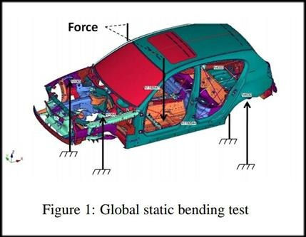
During a global bending test, forces are applied at the front seat locations, while the body is constrained at front and rear shock towers, as shown in figure 1. The static bending stiffness results from the ratio of the applied load to the maximum deflection along the rocker panel and tunnel beams.
Torsional Stiffness-
Measured over the wheel base
Open top cars have poor torsional stiffness
Torsional stiffness is low when:
structure moves up and down and/or whip
parked on uneven ground doors fail to close
doors fail to close while jacking if jack points are at a corner.
Torsion stiffness is influenced by windscreens and reduces by 40% when windscreens removed.
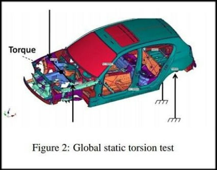
For global static torsion stiffness, a static moment is applied to the body-in-white at the front shock towers, whereas the rear shock towers are constrained, as shown in figure 2.
The torsion angle is defined as the resulting deformation angle between the front and rear shock towers. The corresponding torsion stiffness can be calculated as the ratio of applied static moment to the torsion angle.
Relation of the angle of twist to the applied torque.
T = JθG/L
(where, J= polar moment of inertia; θ = resultant twist of the shaft; G= shear modulus of the material; L= the length of the shaft)
Designing of chassis:
It involves four inter-related steps:
Visualization of properties of chassis
Selecting material
Specifying optimized shape by structural analysis
Choosing manufacturing process
Material Selection-
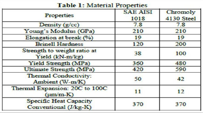
Material selection is an important section of designing, which should be based on some certain properties like:
1. Material properties-
Density (g/cc): The density of the alloy will determine how much a component of a certain size will weigh.
Young’s Modulus (GPa): The stiffness of a metal is often measured by the Young’s Modulus, which compares the relationship between stress (the force applied) and strain (the resulting deformation). The higher the modulus – meaning greater stress results in proportionally lesser deformation – the stiffer the material.
Elongation at break (%):
i. Elongation at break, also known as fracture strain, is the ratio between changed length and initial length after breakage of the test specimen.
ii. The elongation at break can be determined by tensile testing.
Hardness: Hardness is defined as a material’s ability to resist permanent plastic deformation. Typically, the harder the material, the better it resists wear or deformation. The term hardness, thus, also refers to local surface stiffness of a material or its resistance to scratching, abrasion, or cutting.
Toughness: Measured using the Charpy impact test similar to Impact Resistance, toughness represents a material’s ability to absorb impact without fracturing at a given temperature.
Strength to weight ratio (KN-m/kg)
The specific strength is a material's strength (force per unit area at failure) divided by its density. It is also known as the strength-to-weight ratio or strength/weight ratio or strength-to-mass ratio.
Yield Strength (MPa): The yield strength or yield stress is a material property and is the stress corresponding to the yield point at which the material begins to deform plastically. The yield strength is often used to determine the maximum allowable load in a mechanical component.
Thermal Conductivity Ambient (W-m/K): Thermal conductivity is a measure of the quantity of heat that flows through a material. It is measured as one degree per unit of time, per unit of cross-sectioned area, per unit of length.
Thermal Expansion: Thermal expansion is the tendency of matter to change its shape, area, volume, and density in response to a change in temperature, usually not including phase transitions
thermal expansion 𝛼𝐿= dL/LdT
(where L= particular length measurement, dL= change in length, dT= change in temperature).
2. Material cost and availability-
It is an important property of material to consider for the most optimized chassis fulfilling all of our desirable criteria.

3. Processing-
Machinability is the ease with which a metal can be cut (machined) permitting the removal of the material with a satisfactory finish at low cost.
Weldability is considered as ease of accomplishing a satisfactory weld joint and can be in determined from quality of the weld joint, effort and cost required for developing the weld joint.
Castability
Castability is the ease of forming a quality casting.
A very castable part design is easily developed, incurs minimal tooling costs, requires minimal energy, and has few rejections.
Material properties that influence their castability include their pouring temperature, fluidity and solidification shrinkage.
Structural analysis-
1. Simple Structural Surfaces (SSS) method-
With the help of this method, one can determine the loads on the main structural members of an integral structure. Although this type of structure is highly redundant, it is possible by careful representation of the main elements in the structure to determine loads and stress by the simple equations of statics. An SSS is ‘rigid’ in its own plane but ‘flexible’ out of plane. That is, it can carry loads in its plane (tension, compression, shear, bending) but loads normal to the plane and bending out of the plane are not possible.

Stiffening of the panel by swaging or a reinforced hole can increase the load capacity.
The pin-jointed framework will also provide suitable structural properties for the loads
A ring frame (windscreen) provides, sufficient corner joint stiffness and side beam stiffness.
2. Finite element analysis-
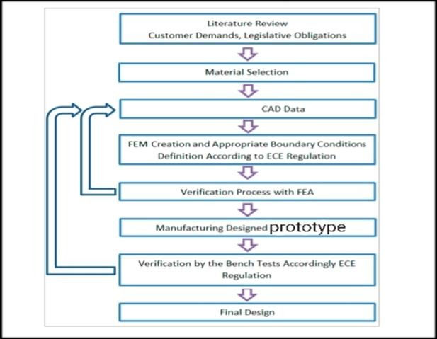
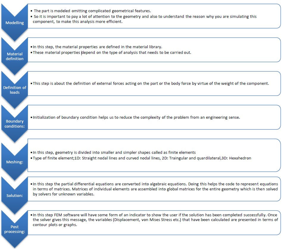
The finite element method (FEM) is the most widely used numerical method for solving problems of engineering and mathematical model like the traditional fields of structural analysis.
It is a part of CAD, which is accepted across the wide range of industries. The methodology of designing is;
It is being used to-
understand the physical behaviors of a complex object (strength, heat transfer capability)
predict the performance and behavior of the design;
calculate the safety margin;
identify the weakness of the design accurately;
identify the optimal design
Manufacturing Process-
Manufacturing process selection should be based on:
Material
Chassis geometry
Number of parts
Tool and material cost
Required level of automation
Types:

Bình luận